Serial Port Multiplexer Arduino
Replacement: None. We are no longer carrying this breakout board in our catalog.
Serial port multiplexer over TCP. This is a set of simple utilities used to let several programs share access to a device connected to a single serial port. Included: A server, which manages the serial port and shares it over TCP with any number of clients.

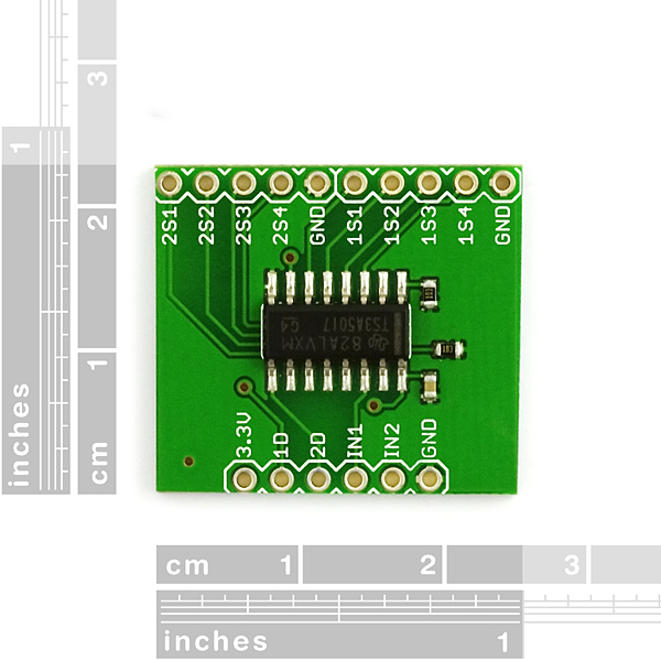
This page is for reference only. This is a breakout board for the TS3A5017 Serial Multiplexer.
The TS3A5017 is a dual single-pole quadruple-throw (4:1) analog switch that is designed to operate from 2.3 V to 3.6 V. This device can handle both digital and analog signals, and signals up to V+ can be transmitted in either direction. Features:. Isolation in the Powered-Down Mode, V+ = 0. Low ON-State Resistance (10 Ohm). Low Charge Injection.

Excellent ON-State Resistance Matching. Low Total Harmonic Distortion (THD). 2.3-V to 3.6-V Single-Supply Operation. Latch-Up Performance Exceeds 100 mA. In 2003, CU student Nate Seidle blew a power supply in his dorm room and, in lieu of a way to order easy replacements, decided to start his own company. Since then, SparkFun has been committed to sustainably helping our world achieve electronics literacy from our headquarters in Boulder, Colorado. No matter your vision, SparkFun's products and resources are designed to make the world of electronics more accessible.
In addition to over 2,000 open source components and widgets, SparkFun offers curriculum, training and online tutorials designed to help demystify the wonderful world of embedded electronics. We're here to help you start something.
Here is an extract of the code to multiplex 5 serial ports in software on an Arduino Duemilanove: It’s a big bag of tricks, really. There is a timer running at 3x the baudrate, which detects start bits and then picks out data bits every three ticks. The crucial issue for the receivers is that the work is done in parallel for 5 input streams, but that these events are not happening at the same time. There are in fact 5 little state machine, each with their own independent state.
For the output, it’s slightly simpler: a buffer with all the 5 transmit bit states is scanned and sent out. The trick here is to fill that buffer with the proper bit patterns. When nothing is sent on a channel, its corresponding bit remains high in all values in the buffer.
Serial Port Multiplexer Arduino Code
The transmit buffer has 30 entries, 3 per bit plus the start and stop bits. A simplification here is that all bytes are sent at the same time, i.e. Start and stop bits occur at the same time on all active transmit channels. The idea of multiplexing is that all received data is collected and sent out to the main (hardware) serial port, running at 57600 baud.
Arduino Multiplexer
Extra character codes 0x01. 0x05 are inserted into the multiplexed data stream to identify from which channel the data is coming. On the transmit / de-multiplexing side, the character codes 0x01. 0x05 are filtered out and used to indicate to which channel to send out the next characters. If you connect two of these multiplexing shields back-to-back, you can send 5 independent bi-directional serial streams over a single 3-wire cable.

Come to think of it, the following setup would make a great test for these multiplexing shields: The full source code for the multiplexing sketch can be found. It has been tested at 9600 baud (all receivers must run at the same speed). It probably works at higher speeds even, but this hasn’t been tested. At some point, the Atmega chip is going to get swamped while handling the barrage of timer 1 interrupts. I haven’t really tested the transmit part yet, i.e. The de-multiplexing side of things.